Modern metallurgy faces intense margin pressures today. High energy consumption directly erodes plant profitability. Unplanned downtime causes massive production losses across the floor. Many facilities still rely on legacy Direct-On-Line (DOL) starters. They use outdated mechanical speed controls for their critical applications. These older systems cannot meet modern operational demands. Steel plants require tight process control and rapid load balancing. Rigid electrical setups introduce severe mechanical stress. You need a smarter approach to handle these dynamic industrial loads. Upgrading to Variable Frequency Drives provides an immediate and robust solution. It is not just a simple energy-saving measure. It remains a critical requirement for precise torque control. You will learn how these systems drastically extend equipment longevity. We will explore how they maintain product consistency in harsh metallurgical environments.
Key Takeaways
Process Precision: Implementing VFDs resolves multi-motor load imbalances—such as those caused by asymmetric rolling speeds—drastically reducing mechanical stress and localized overheating.
Energy Recovery: Shared DC bus architectures allow energy from braking sections to power active rolling sections, driving systemic power consumption down.
Targeted Deployment: Selecting the correct drive—ranging from a general vector frequency converter for main lines to an economy vector frequency converter for auxiliary pumps—optimizes the capital expenditure (CapEx) to return on investment (ROI) ratio.
Risk Mitigation: Successful deployment requires upfront planning for harmonic distortion, grid stability, and motor insulation limits.
The Operational Baseline: Why Legacy Mill Drives Drain Margins
Static-speed mill operations carry massive hidden costs. Plant managers often overlook the friction between required process adjustments and rigid electrical setups. Legacy electrical configurations force motors to operate at full speed regardless of actual load requirements. This rigidity creates severe bottlenecks. Operators must rely on mechanical dampers or gearboxes to regulate output. Mechanical regulation wastes an enormous amount of power. It also introduces constant wear and tear. You lose operational flexibility when your electrical architecture cannot adapt instantly to physical material changes.
The industrial reality of asymmetric rolling perfectly illustrates this problem. Operators intentionally offset upper and lower roller speeds during production. They do this to prevent the hot metal from bending downward as it exits the stand. Industry experts refer to this downward bending as the "ski effect." Preventing this effect requires immense precision. You must maintain a slight, calculated speed difference between the rollers. Legacy systems struggle to manage this delicate multi-motor imbalance. They fight against the intentional speed offsets, creating opposing forces.
This struggle leads to significant operational impact. A tiny five percent speed deviation in legacy systems causes a massive two-fold torque mismatch. One motor suddenly takes on twice the physical load. This pushes the motor into severe overload conditions. It wastes energy and degrades the internal winding insulation rapidly. Meanwhile, the companion motor underperforms and idles inefficiently. This imbalance destroys the systemic efficiency of the rolling stand. Your plant pays for power it never effectively uses.
Mechanical stress compounds these operational losses over time. Direct-On-Line starting transients hammer the mechanical driveline. When you start a motor across the line, it draws up to six times its nominal current. This massive surge jolts the entire system. Gearboxes, bearings, and heavy-duty belts take massive shock loads. These transients fracture gear teeth and ruin bearing races prematurely. The lifecycle costs of maintaining this battered equipment quickly outweigh any perceived savings from keeping older technology.
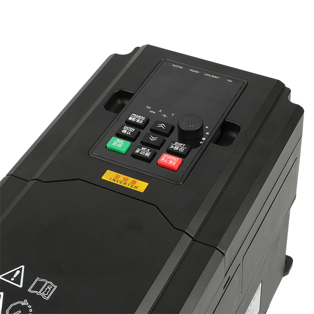
Engineering the Solution: How Variable Frequency Drives Optimize Mill Processes
Modern electrical infrastructure transforms how metallurgical plants operate. We can map specific technological features directly to measurable operational outcomes. You gain unprecedented control over every phase of the rolling process.
Direct Torque Control (DTC) and Advanced Motor Control: This translates to sub-millisecond load alignment. The system monitors the magnetic flux and motor torque continuously. It forces connected motors to share dynamic loads symmetrically. This keeps them operating securely within their peak efficiency windows. You eliminate the severe two-fold torque mismatches commonly seen in asymmetric rolling setups.
Common DC Bus Configurations: This topology connects multi-drive systems intelligently. Regenerative energy from decelerating mechanical sections flows backward. For example, braking shears or uncoilers generate excess power. The shared bus captures this energy. It feeds the power directly into accelerating rolling sections. You recycle power internally instead of bleeding it off as waste heat.
Soft Starting Capabilities: Intelligent ramping eliminates high-current starting spikes. The drive gradually increases the frequency and voltage supplied to the motor. This protects the electrical grid from severe demand-peak penalties. It also shields the mechanical driveline from brutal shock loads. Belts last longer, and gearboxes require less frequent servicing.
Affinity Law Applications: We see high-yield energy savings on auxiliary variable-torque loads. Think of your cooling bed fans and scale pit pumps. These applications follow the physical affinity laws. A mere twenty percent reduction in motor speed yields nearly a fifty percent reduction in energy use. The cubic relationship between speed and power consumption makes this highly lucrative.
These engineered outcomes create a resilient, adaptable production line. You stop fighting the physics of the mill. Instead, you synchronize the electrical delivery with the exact mechanical demand of the steel.
Matching Drive Class to Application: General vs. Economy Topologies
Buyers must avoid over-engineering or under-specifying their electrical equipment. Process criticality dictates the exact hardware topology required. You must align the drive capabilities with the specific environmental and operational demands of each mill section. Different zones require drastically different approaches.
Main mill drives demand heavy-duty, highly specialized configurations. Primary rolling stands and massive industrial shears handle extreme forces. They require exceptionally high overload capacities. You need encoderless precise torque response to manage sudden material impacts. Furthermore, these units face severe airborne metallic dust. Robust cast-iron enclosures are mandatory to protect the delicate power electronics inside. Standard commercial enclosures will fail rapidly in these primary zones.
Intermediate applications require a balanced approach. A General Vector Frequency Converter fits these mid-tier demands perfectly. Heavy conveyors and cooling bed drives rely on them heavily. In these applications, reliable speed tracking is essential to maintain material flow. Moderate overload capacity remains non-negotiable to clear occasional mechanical jams. They provide excellent control without the extreme specialized costs of a primary stand unit.
Auxiliary systems follow an entirely different specification logic. Basic water pumps, HVAC units, and light material handling conveyors operate under lighter demands. An Economy Vector Frequency Converter works best for these peripheral tasks. Capital constraints usually dictate choices in this category. Standard Volts-per-Hertz (V/f) or basic vector control proves entirely sufficient. You do not need sub-millisecond torque response to run a simple ventilation fan.
Below is a quick reference table detailing how to match the drive class to the application:
Drive Class | Primary Application | Overload Requirement | Control Topology |
Heavy Duty / Specialized | Main rolling stands, primary shears | High (150% - 200%) | Advanced DTC / Closed-loop |
General Vector | Heavy conveyors, cooling beds | Moderate (120% - 150%) | Sensorless Vector Control |
Economy Vector | Auxiliary pumps, HVAC, fans | Low to Moderate (110% - 120%) | Standard V/f / Basic Vector |
Implementation Realities: Harmonics, Insulation, and Grid Stability
We must take an unvarnished look at the engineering challenges of retrofits. Implementing modern power electronics introduces specific physical risks to legacy plants. You must address these realities proactively during the design phase. Ignoring them leads to catastrophic equipment failures.
Grid distortion presents the most immediate challenge. Non-linear electrical loads introduce significant harmonic noise into your plant grid. The drive rectifiers pull current in short, heavy pulses. This distorts the perfect sine wave of your incoming power. You must outline strict evaluation criteria for harmonic mitigation. Consider utilizing 18-pulse drives for massive loads. Active Front Ends (AFE) actively cancel out harmonic noise. For smaller units, specifying three to five percent line reactors helps suppress distortion adequately.
Motor insulation limits dictate your retrofit success. Modern Pulse Width Modulation (PWM) drives switch voltages incredibly fast. This creates a phenomenon known as reflected waves. It causes extreme voltage rise times across the motor cables. We refer to this as high dv/dt stress. Do not pair modern PWM equipment with pre-existing, standard-duty motors. The voltage spikes will punch through old insulation rapidly. We highly recommend specifying "Inverter Duty" motors that comply with NEMA MG1 Part 31 standards. This precaution prevents premature winding insulation failure.
Low-speed thermal management requires careful planning. Legacy motors rely on internal cooling fans attached directly to their rotor shafts. When you operate the equipment at consistently low speeds, these internal fans lose their cooling efficacy. The motor continues to generate heat, but the fan cannot clear it. The motor overheats quickly. You must evaluate external forced-air cooling requirements. Dedicated electric blowers ensure adequate airflow regardless of the primary rotor speed.
Evaluating Implementation Success and Next Steps
You must move beyond simply measuring the initial purchase price. Plant managers need a robust framework to evaluate long-term operational success. A successful deployment completely changes your maintenance and utility baselines. You need specific metrics to prove the upgrade worked.
First, evaluate direct energy reductions. Track the raw kilowatt-hour drop across the upgraded sections. Next, monitor the elimination of peak-demand utility charges. Soft starting directly prevents the massive current spikes that trigger these utility penalties. Finally, quantify the reduction in unplanned mechanical maintenance. Count the extended lifespan of your belts, bearings, and critical gearboxes. These operational savings compound heavily year over year.
Procurement and engineering teams must follow strict shortlisting logic. Demand specific pilot data before attempting a site-wide rollout. You need actionable proof of concept.
Audit Category | Key Action Item | Expected Outcome |
Thermal Profiling | Conduct thermal imaging of motor windings | Identify hotspots and verify cooling efficacy at low speeds. |
Power Quality | Perform site-wide harmonic distortion audit | Ensure THD (Total Harmonic Distortion) stays within IEEE 519 limits. |
Vibration Analysis | Baseline mechanical resonance frequencies | Avoid programming operational speeds that trigger mechanical resonance. |
Your immediate next-step action is clear. Do not buy hardware blindly. Recommend scheduling an on-site harmonic audit first. Establish a rigorous baseline energy assessment with a certified system integrator. This ensures you document the exact inefficiencies of your current setup before installing new equipment.
Conclusion
Deploying advanced power electronics represents a strategic lifecycle investment. It is never a plug-and-play commodity purchase. The harsh realities of metallurgical production demand highly engineered solutions. The technology drastically improves precision, balances heavy loads, and protects your mechanical driveline from destructive transients.
Realizing these promised efficiency gains requires a strictly holistic approach. You must match the right converter topology perfectly to the specific physical load. Furthermore, you must proactively manage electrical harmonics and thermal realities. By thoroughly planning the integration, your facility will achieve unprecedented control, stability, and operational longevity.
FAQ
Q: How does a VFD handle the high shock loads of a reversing rolling mill?
A: Modern drives use advanced vector control loops and torque-proving algorithms. They pre-magnetize the motor instantly before the metal strikes the rollers. The controller dynamically adjusts current to meet instantaneous load spikes. It responds in sub-milliseconds, providing massive breakdown torque without tripping overcurrent protections or stalling the process.
Q: Can we retrofit a General Vector Frequency Converter onto our existing mill motors?
A: You must proceed with caution. Always check your existing motor insulation classes first. The motor must comply with NEMA MG1 Part 31 standards to handle high-frequency voltage spikes (dv/dt). You also must verify the motor's cooling capacity at lower speeds to prevent catastrophic dielectric breakdown.
Q: What is the expected payback period for an Economy Vector Frequency Converter on mill auxiliary pumps?
A: Payback periods typically range from 12 to 24 months. This rapid return relies on the affinity laws for variable-torque pump and fan loads. Because energy consumption drops by the cube of the speed reduction, even small speed decreases yield massive energy savings, depending on your local utility rates.
Q: How do multi-drive VFD systems impact plant power quality?
A: Individual non-linear drives introduce harmonic distortion into the grid. However, modern multi-drive systems utilize shared DC buses and Active Front Ends (AFE). These advanced front ends actively cancel harmonic noise. They can even correct the plant's overall power factor, improving aggregate power quality.


